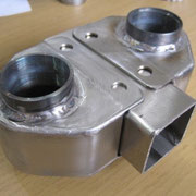
Construction of 2 bottom brackets
The two bottom brackets should not be welded into the frame, but moved on the frame (advantageous for subsequent chain tension and for the adjustability of leg
lengths with modified seat tilt.).
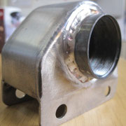
It is the only part of the entire frame, which contains a component of a stainless steel (25 CrMo 4), because I had none of stainless steel. I'll name it frame
threads pipe. For this reason, the bottom bracket shall get after the construction of the overall component powder coating in (www.goetz-pulverbeschichten.de). The powder coating, zinc primer
with top coat = a novel "Translucent-red". The selection is based on its similarity with the red anodized surface of hub gear, hubs, headset and other small parts. It should be color coordinated
everything on red, gray (stainless steel natural) and black.
This little welding assembly must have very tight tolerances (sliding seat on the frame) at the end to ensure good power transmission.


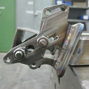
Construction of suspension swing-arm
In the whole building process is the most difficult part, if the bike is to be fully suspended. Here dimensional accuracy, rigidity and torsional strength required.
Especially in view of the subsequent use of disc brakes.
It starts with the preparation work here. What I need:
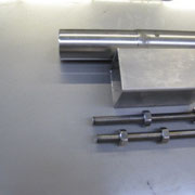
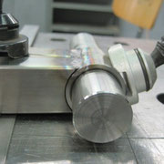
• Center of rotation from the swing arm: turned parts, bearings, mounting.
• Semi-finished products for all struttings. In this case, rectangular tube 30x20x2 in 1.4301.
• Dropouts that can be purchased to match the Rohloff Gear look for in company Lauble and Fichter ( www.lauble-fichter.de) also available in 1.4301. Also in order to details, such as: Do I
want to attach a disc brake? Or: Do I need despite hub gears still a chain tensioner back (because of the length of the chain)?
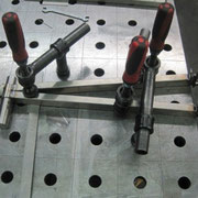
• Support through small apparatus and clamping tools (see photos).
Job breakdown:
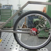
First, put the rear wheel at approximate position (in line and distance) to the frame. For this one needs a helping hand sometimes. Observe the subsequent pitch of spring. Now, the axial distance between the center of rotation of the swing arm and the dropouts is measured (length for the cutting of
rectangular tube).
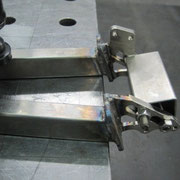
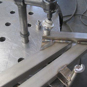
The dropouts are adapted to their connection with the rectangular tube with the disc grinder and two small connection metal sheets (see also photo " swing arm- cutting first parts)
prepared.
Now:
translation soon...
- Drehteile der Rahmen-Achsbefestigung fixieren
- Ausfallenden am vorgefertigten Hinterrad in richtiger Position mit Schnellspanner befestigen
- Abstand zwischen beiden Punkten messen und Rechteckrohr passend zuschneiden
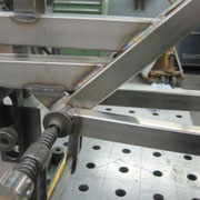
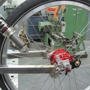
Die gefederte Hinterradschwinge sollte bei "TWOgether One" den Federweg von 50 mm haben. Dazu kaufte ich entsprechend im Vorfeld 2 Dämpfer (Suntour Hinterraddämpfer RS9 Epicon LOD 190). Sie waren das letzte Bindeglied beim Rahmenbau. Die Größe des kleinen Dreiecks am Heck der Schwinge war davon abhängig.
Die Dämpfer mussten auf volle Länge ausgefahren sein. Nun 2 kleine vorgefertigte Sättel an die Achspunkte des Dämpfers geschraubt (sichtbar auf Bild: "Vorbereitung + Maßnehmen für die Dämpfer") und das kleine Dreieck zum Ausfallende vermessen, aus Rechteckrohr zuschneiden, verschweißen und am Ausleger der Schwinge mit Schweißpunkten nur anheften.
Auch die beiden oberen Achspunkte der Dämpfer am Rahmen nur anheften.
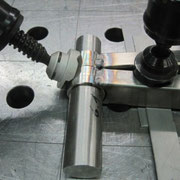
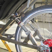
Die Problematik: Vor dem Verschweißen der "Achspunkte" der Dämpfer muß auf den Achstand des Hinterrades geachtet werden (s. Bild: "Fluchtkontrolle und Richtarbeiten"). Man kann später auch noch durch Richtarbeiten an der Schwinge kleine Korrekturen durchführen. Aber annähernd sollte es schon im Vorfeld stimmen!
Komplett fertiggeschweißt wird die Schwinge erst, wenn die Flucht des Hinterrades stimmt.
Zwei wichtige Punkte, die noch zu beachten sind:
- Bei Verwendung von Edelstahl muß man den größeren Verzug der Bauteile beachten und einen größeren späteren Richtaufwand eventll. in Kauf nehmen!
- Deshalb ist es wichtig, die Bauteile während des Schweißens und abschließenden Abkühlens gut zu fixieren!